
Description
Number of Pages: 48
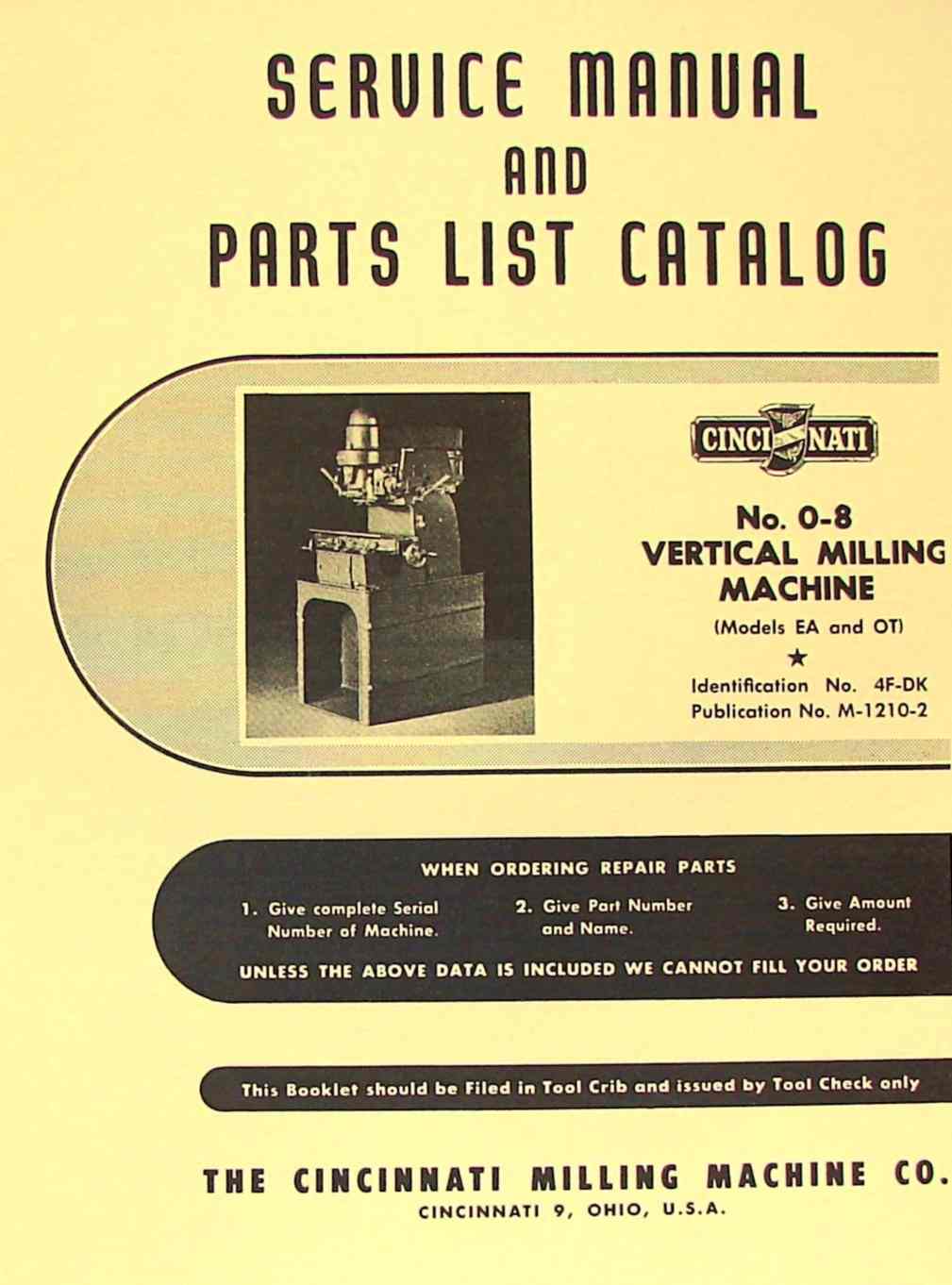
This is a reproduction, not a photocopy, of an original Cincinnati No. 0-8 Vertical Milling Machine for Models EA and OT Service Manual and Parts List Catalog. If you own this mill you need this manual! This manual contains information on setup, lubricating, maintenance, and controls as well as a complete parts list and exploded views and adjustments. This manual goes into great detail about dismantling and adjustments. As well as running all of the complex movements of this machine. The lubrication and parts list are also excellent. This is one of the most informative manuals I have seen. This manual would honestly be a big help to anyone who owned this mill.

Content
1. ADJUSTMENTS
To Adjust and Disengage Backlash Eliminator…………………….15-16
To Adjust Gibs…………………………………………………14
To Adjust Spindle Bearing……………………………………….14
To Adjust Spindle Drive Belt…………………………………….17
To Adjust Table Lead Screw Bearings………………………………15
To Adjust Table Rapid Traverse Clutch…………………………….16
2. DIAGRAMS AND ILLUSTRATIONS
Dimensional Drawing……………………………………………..6
Functional Diagram and Oiling Stations………………………..8-9-10
Looking Into Table Bed Drive Gear Unit……………………………28
Spindle Carrier Lubricating Oil Piping……………………………29
3. DISMANTLING INSTRUCTIONS
For Spindle Carrier Unit Remove and Dismantle Cross Feed Control…………………………..19
Remove and Dismantle Quill Adjusting Mechanism…………………….18
Remove and Dismantle Quill and Spindle……………………………20
Remove Spindle Carrier………………………………………….18
Remove Spindle Carrier Lead Screw………………………………..22
Remove Spindle Sleeve…………………………………………..21
For Table Bed Unit Remove Bevel Gear Shaft…………………………………………24
Remove and Dismantle Lubricating Pump…………………………….23
Remove and Dismantle Main Drive Shaft…………………………….25
Remove Rapid Traverse Shift Mechanism…………………………….27
Remove Table Bed Motor and Coolant Pump…………………………..26
Remove Table Drive Gear…………………………………………26
Remove Table Feed Change Gear Shafts……………………………..27
Remove Table and Lead Screw……………………………………..23
4. INSTALLATION INSTRUCTIONS………………………………….11-12
5. LUBRICATION INSTRUCTIONS AND SPECIFICATIONS…………………….13
6. MACHINE SPECIFICATIONS………………………………………..7
7. PRINCIPAL DIMENSIONS OF CAP SCREWS, NUTS AND SET SCREWS USED……..12
8. CONVERSION TABLE……………………………………………..4
PARTS LIST CATALOG
1. HOW TO ORDER REPAIR PARTS…………………………………….31
2. COOLANT PUMP AND PIPING (Unit Nos. 4FP-APA)………………….42-43
3. MACHINE INSTRUCTION AND NAME PLATES……………………………46
4. MOTOR DRIVE (Unit No. 4FN)…………………………………40-41
5. CIRCULAR MILLING ATTACHMENT (Unit No. 4FGJ)………………….44-45
6. SPINDLE CARRIER (Unit No. 4FV)……………………………..38-39
7. TABLE BED (Unit No. 4FB)…………………………………..32-37
Overview
I have collected this information for many years and have found the information they contain to be priceless in using and setting up the machines properly. I believe this manual will be a valuable resource of knowledge that will provide a lot of helpful information that is often hard to find. My manuals are not photocopies. I maintain a high standard of quality in my reproductions. Most of the manuals I reproduce look better than their originals. I have professionally digitally edited every page,and removed stains, wrinkles and handwriting. All of the manuals are printed on thick white paper to withstand shop wear and tear; they are then comb bound with heavy cover pages so they lie flat on the workbench.