Description
Number of Pages: 114
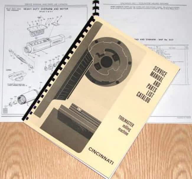
This is a reproduction, not a photocopy, of an original Cincinnati Toolmaster Milling Machine 1B, 1C, 1D, 1E, H-V Service and Parts Manual. This manual contains general safety instructions, operation instructions, adjustments, maintenance, and a complete set of exploded view part diagrams with descriptions. See index below.

Contents:
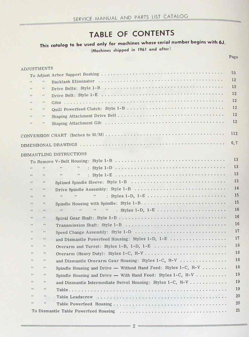
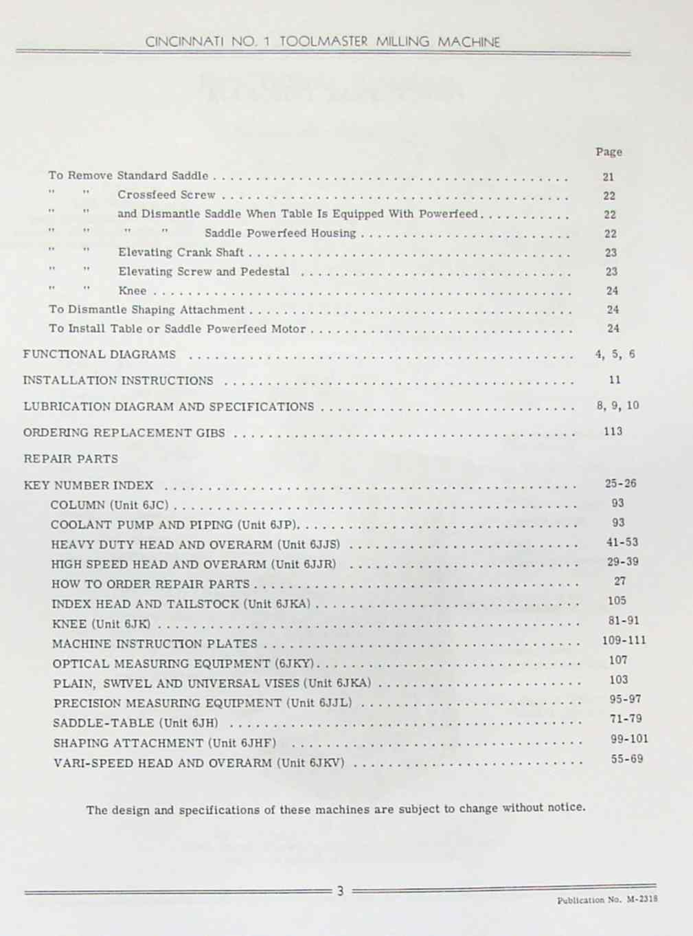
ADJUSTMENTS
To Adjust Arbor Support Bushing...........................................3
 "   "    Backlash Eliminator............................................12
 "   "    Drive Belts: Style 1-B.........................................12
 "   "    Drive Belt: Style 1-E..........................................12
 "   "    Gibs...........................................................12
 "   "    Quill Powerfeed Clutch: Style 1-B..............................12
 "   "    Shaping Attachment Drive Belt..................................12
 "   "    Shaping Attachment Gib.........................................12
CONVERSION CHART(Inches to M/M).........................................112
DIMENSIONAL DRAWINGS....................................................6,7
DISMANTLING INSTRUCTIONS
To Remove V-Belt Housing: Style 1-B......................................13
 "   "      "      "    : Style 1-D......................................13
 "   "      "      "    : Style 1-E......................................13
 "   "    Splined Spindle Sleeve: Style 1-B..............................13
 "   "    Drive Spindle Assembly: Style 1-B..............................14
 "   "      "      "    : Styles 1-D, 1-E................................15
 "   "    Spindle Housing with Spindle: Style 1-B........................15
 "   "      "      "    : Styles 1-D, 1-E................................16
 "   "    Spiral Gear Shaft: Style 1-B...................................16
 "   "    Transmission Shaft: Style 1-B..................................16
 "   "    Speed Change Assembly: Style 1-D...............................17
 "   "    and Dismantle Powerfeed Housing: Styles 1-D, 1-E...............17
 "   "    Overarm and Turret: Styles 1-B, 1-D, 1-E.......................18
 "   "    Overarm (Heavy Duty): Styles 1-C, H-V..........................18
 "   "    and Dismantle Overarm Gear Housing: Styles 1-C, H-V............18
 "   "    Spindle Housing and Drive - Without Hand Feed: Styles 1-C, H-V.18
 "   "    Spindle Housing and Drive -With Hand Feed: Styles 1-C, H-V.....19
 "   "    and Dismantle Intermediate Swivel Housing: Styles 1-C, H-V.....19
 "   "    Table..........................................................19
 "   "    Table Leadscrew................................................20
 "   "    Powerfeed Housing..............................................20
To Dismantle Table Powerfeed Housing.....................................21
To Remove Standard Saddle................................................21
 "   "    Crossfeed Screw................................................22
 "   "    and Dismantle Saddle When Table Is Equipped With Powerfeed.....22
 "   "      "      "    Saddle Powerfeed Housing.........................22
 "   "    Elevating Crank Shaft..........................................23
 "   "    Elevating Screw and Pedestal ..................................23
 "   "    Knee...........................................................2
To Dismantle Shaping Attachment..........................................24
To Install Table or Saddle Powerfeed Motor...............................24
FUNCTIONAL DIAGRAMS ..................................................4,5,6
INSTALLATION INSTRUCTIONS ...............................................11
LUBRICATION DIAGRAM AND SPECIFICATIONS...............................8,9,10
ORDERING REPLACEMENT GIBS...............................................113
REPAIR PARTS KEY NUMBER INDEX.........................................25-26
COLUMN (Unit 6JC)........................................................93
COOLANT PUMP AND PIPING (Unit 6JP).......................................93
HEAVY DUTY HEAD AND OVERARM (Unit 6JJS)...............................41-53
HIGH SPEED HEAD AND OVERARM (Unit 6JJR)...............................29-39
HOW TO ORDER REPAIR PARTS................................................27
INDEX HEAD AND TAILSTOCK (Unit 6JKA)....................................105
KNEE (Unit 6JK).......................................................81-91
MACHINE INSTRUCTION PLATES..........................................109-111
OPTICAL MEASURING EQUIPMENT (6JKY)......................................107
PLAIN, SWIVEL AND UNIVERSAL VISES (Unit 6JKA)...........................103
PRECISION MEASURING EQUIPMENT (Unit 6JJL).............................95-97
SADDLE-TABLE (Unit 6JH)...............................................71-79
SHAPING ATTACHMENT (Unit 6JHF)...................................... 99-101
VARI-SPEED HEAD AND OVERARM (Unit 6JKV)...............................55-69


Overview
I have collected this information for many years and have found the information they contain to be priceless in using and setting up the machines properly. I believe this manual will be a valuable resource of knowledge that will provide a lot of helpful information that is often hard to find. My manuals are not photocopies. I maintain a high standard of quality in my reproductions. Most of the manuals I reproduce look better than their originals. I have professionally digitally edited every page,and removed stains, wrinkles and handwriting. All of the manuals are printed on thick white paper to withstand shop wear and tear; they are then comb bound with heavy cover pages so they lie flat on the workbench.