Posted on

10″x50″ Vertical Milling Machine Restoration Part: 2 Cleaning and Painting :Shop Projects

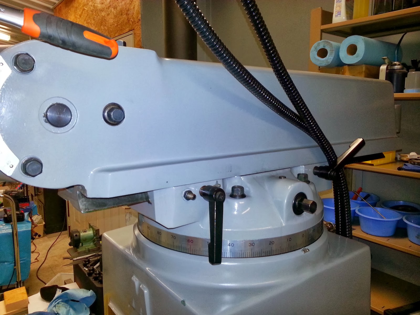
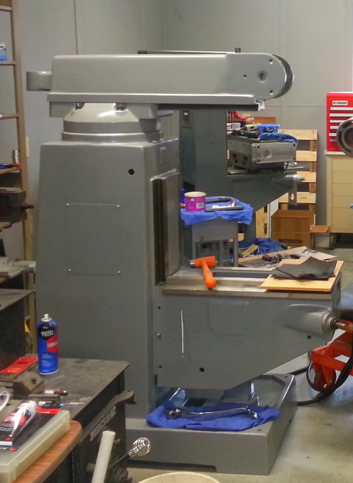
We are now ready to clean, paint, and restore our new Grizzly G4029 10×50 vertical milling machine. After finally getting the mill moved into our shop (Part 1), we kept the mill on the flat dolly to make it easier to move and paint until we figure out where it’s permanent home would be located.

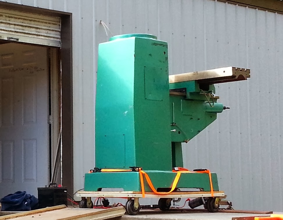
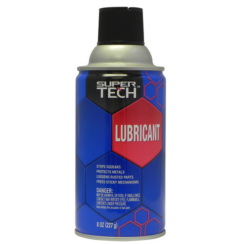
This milling machine has never been used, but it had at least 5 year old cosmoline grease on it to prevent rusting. Some of it was so thick and gummy that we had to use some razor blades to scrape a lot of it off, and then we used some rags with the Super Tech lubricant that they sell at Walmart. It really helped loosen the cosmoline and helped with any small amounts of rust that did form. It’s just like WD-40, but cost less. We have ended up using it quite a bit with the machines in our shop.

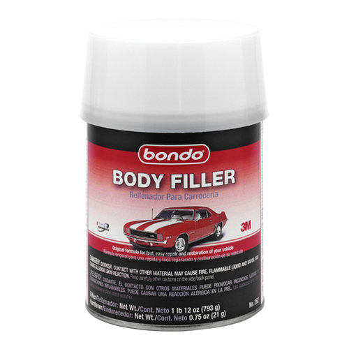
We decided to take the time to sand, putty, and paint the entire mill. There were a lot of chips and scratches in the paint and casting putty from being stored and moved around the Grizzly warehouse for years. Plus, we aren’t big fans of the green paint. We disassembled every part except the knee. We sanded everything, and used the Bondo Lightweight Body Filler to fill in the chips and scratches.

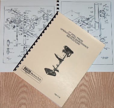
  • Please Note: It is actually a good idea to disassemble spindles and critical parts of any Asian machine to clean them and grease/oil them properly. You may not believe the amount of grit and grime left from the manufacturing process in these. I would NEVER operate an Asian machine without doing this.
I like using this Bondo, because it states that it works with metal and steel, and it’s fairly easy to use and manipulate. I recommend building it up in layers on good size chips or holes (build and sand, build and sand). It’s nearly impossible to get it correct the first time for the paint.
Before we decided on the new color of our mill, we had to make some decisions about the milling head. The head to our G4029 mill had been cannibalized for parts over the years, which is a common practice at Grizzly on damaged machines. We decided the best option for our shop and time was to purchase a brand new head with the options we really need/want. I’ll discuss more about finding and ordering parts for these types of mills in the next article, but we ended up choosing the ACER E-Mill 3HP Variable Speed Head, which cost a little over $3,000. They are available in Bridgeport gray or beige.
We decided to go for the Bridgeport gray color. A good easily accessible paint that is very close to Bridgeport gray that we decided to use is Krylon “ColorMaster Classic Gray Spray Paint”. It is also available at Walmart. It goes on easily, and we have found it to be fairly durable in the shop.
Here are some pictures of the finished results. I’ll have a lot better pictures in the next article about parts and installation of the new mill head.

Do you have any products that you like to use during your machine restoration and painting? Or do you have any recommendations for me? Do you have any tips or tricks?

Please share in your comments below.
Posted on 9 Comments

Machine ID’d: Rockwell-Delta 17″ Drill Press with DP-600 casting.

rockwell17drillpress1

Rockwell17drillpress1

Here is a old Rockwell-Delta 17″ floor model drill press that a reader sent us pictures of to find more information about. The owner said the Rockwell drill press was used in a production facility for some time. The gentleman he bought the drill press from was 67 and said he started operating it when he was 13. This Rockwell 17″ drill press has has serial number 79-794 which dates it to 1949. In 1950 this drill press sold for $180.50 to $196.00 depending on the options, which is equivalent to $1,745.60 to $1,895.50 today. In 1949, you couldn’t pick up a quality machine like this in a garage sale.


Delta17drillpress1


It appears that this particular Rockwell-Delta 17″ drill press has a slow speed attachment, which is the pulley installed right above the column, but there is pulley on the motor with only one position. I’m not sure if the motor pulley broke at some time or not, but this is not a typical or Rockwell Manufacturing configuration. Information on the slow speed attachment is not included in the main owner’s manual, but it was used to provide more speed options for drilling. I’m guessing someone may have broken the original motor pulley, and either had or found a slow speed attachment to get at at least some speeds out of the drill press.


How to Identify this Rockwell Drill Press

We have operator, owner’s, and parts manuals for many different Rockwell-Delta-Milwaukee drill presses here. These older Delta machines from this vintage usually don’t have model numbers on them, and lots of people have asked us how to identify them.


The simplest way to identify many of these older Delta machines is by the casted part number on the main part of the machine. These Rockwell-Delta 17″ drill presses have “DP-600″ casted into the head on the arm that supports the front pulley. This is the part number for the head casting. Here is a picture showing its location on another 17” drill press.


Manuals for this Rockwell 17″ Drill Press


We have a couple manuals that would be useful with this Rockwell-Delta 17″ drill press model. We have the original operator’s and parts manual for this drill press model here:


DELTA-MILWAUKEE 17″ Drill Press DP-600 Instructions & Parts Manual with FOOT FEED


We also have another book that Delta published with additional information about drill press use and set ups. This book covers all the branches of drill press operation in the home workshop with over two hundred photographic illustrations and line drawings even for uses like sanding, shaping, mortising, etc…


It’s a really useful and interesting series of books that I recommend to anyone wanting to learn more about drill press use.

DELTA Getting the Most Out of Your Drill Press Manual


 Catalog Pages for the Rockwell 17″ Drill Press


Below are some pages from a 1950 Delta Milwaukee catalog about this 17″ drill press. The catalog displays the different options and accessories that were available for this model. The drill press owners manual above covers a lot of the different variations between the bench and floor models.


Pages from delta catalog 1950_Page_1              Pages from delta catalog 1950_Page_2


Do you have one of these drills, or
do you have anything else you would like to add about it’s history or use?
Please add your comments below.


Submit Your Machine
Do you want to know more about your machine?

Email us your details with pictures, and we’ll put together the best information we can find. Plus, we can get other readers’ input to help you learn more.

Also, feel free to email us if you want us to share your machine on our site.

Email your information to: info@ozarkwoodworker.com

Posted on

Machine ID’d: Walker Turner 24″ Scroll/Jig Saw J915

Received these pictures from a gentleman trying to verify which Walker Turner 24″ scroll saw he had in his shop. Walker Turner made a lot of changes to their 24″ scroll saw over time. Some of the difference are fairly subtle, and we have manuals for a few of them. The differences between the J781 and J782 are so subtle that we combined the two into the same manual to make it easier for everyone.

 
The main identifying difference between the J915 and the J781 or J782 is the fact that the air hose comes out of the arm (as you can see in the image below). While the air hose on the J781 and J782 comes out of the top of the head.
We have a manual for this Walker Turner Jig/Scroll saw here:

The Walker Turner J915 24″ Jig Saw without a stand or accessories sold for $63.50 in 1949, which is equivalent to $623.12 today. Here is a page on the J915 from a 1949 Walker Turner catalog.

Do you have one of these scroll saws, or
do you have anything else you would like to add about it’s history or use?
Please add your comments below.

Submit Your Machine
Do you want to know more about your machine?

Email us your details with pictures, and we’ll put together the best information we can find. Plus, we can get other readers’ input to help you learn more.

Also, feel free to email us if you want us to share your machine on our site.

Email your information to: info@ozarkwoodworker.com

Posted on 4 Comments

How To: Measure the Size and Swing of a Wood or Metal Lathe

measuring lathe swing

People often ask us how to measure the size and swing of their wood or metal lathe. Lathes are generally described by the maximum size of material that can be cut or machined on the lathe. Before machining a workpiece, the following measurements must be considered: the diameter of the work that will swing over the bed and the length between lathe centers. Often you will see numbers like 14×40 or 9×42 describing the size of a lathe. So what do these numbers mean?

Wood and Metal Lathe Sizes

How to Measure the Lathe Swing and Size

What does the term “swing” on a lathe mean? The first number is referred to as the swing of the lathe which is the maximum diameter of a piece or work that can fit in the lathe. If you have a lathe and want to measure for the swing, you simply measure from the bed of the lathe to the center of the spindle, and then double that measurement. If you measure 6″, then you have a 12″ swing lathe.

Measure Swing of Metal Wood Lathe


  • Special Note: Sometimes there can be some discrepancies between the actual measured swing and the swing the manufactures label the machine as being. I’ve only seen this on larger geared head metal lathes and European metal lathes. Some foreign lathes were made on metric standards, and they rounded to the nearest US standard size. Some companies labeled them based on the measurement from the top of the cross-slide for the tool holder on the metal lathe to the spindle.  For example this Bradford Metalmaster geared head metal lathe series had actual measured swings of 14.5″, 16.5″, and 18.5″, but Bradford labeled the lathes as 12″, 14, and 16″.


Keep in Mind

On metal lathes, it is important to know the swing over the carriage where your tool holder sits. A lot of companies will give you this specification, and some companies in the past have used this measurement as the size of the “actual” swing of the lathe. It is obvious, if you have to cut something over the carriage of the lathe, it will make your working swing smaller in diameter.

Measure Swing of Metal Lathe


How to Measure Distance Between Centers on a Lathe

The second number in the sequence 14x40 is referred to as the distance between centers. This is the distance between a center in the headstock to a center in the tailstock. This gives you an idea as to how long the working area of the lathe is. However, a lot of companies in the 40’s or before used the size of the bed as the second number.

Measure Distance Between Centers Metal or Wood Lathe

Depending on what tooling and what kind of cuts, drills, bores, etc… you are trying to use can vary the maximum length of material you can work on in your lathe.

Example:

A 10×24 lathe can handle work that has a diameter up to 10″ and a length between centers of 24.”

Remember:
If you need any help identifying your lathe please feel free to send us pictures and information to info@ozarkwoodworker.com. We’ve identified hundreds successfully.
Please feel free to post comments and questions on this post or any ideas or topics you would like to discuss on future post. And if you need a manual for your lathe, we have all of them listed here at the links below:

Need a manual for your lathe?

Select the Wood or Metal Lathe links below.


Wood Metal Lathe Manuals
Posted on 1 Comment

Machine ID’d: Delta-Rockwell 11″ Wood Lathe model 46-230

Received these pictures of a Delta-Rockwell 11″ wood lathe on a nice heavy duty bench top stand. These were sold under the Homecraft division of Delta. They made a few different versions that look similar. The earlier models had a steel stand. This one has a cast iron stand and is a model 46-230. This lathe has a serial number of 85-7014, which dates it manufacturing to 1950.

We have a couple manuals that cover the 46-230 Rockwell 11″ wood lathe. We have the owner’s manual with operating instructions and parts diagrams here:
We actually combined the older and new versions of this lathe in one book. We also have “Getting the Most Out of Your Lathe” book that Delta published. It covers this lathe and shows a lot of tips and tricks for using and setting up your lathe for different cuts. This is one book of a 6 part series we have in stock. Here is the book on the lathe:
This lathe originally sold for $54.95 in 1950. Below is the page on the lathe from a 1950 Delta-Homecraft catalog. According to the inflation calculator this is equivalent to $532.50 today.
Do you have one of these lathes, or
do you have anything else you would like to add about it’s history or use?
Please add your comments below.

Submit Your Machine
Do you want to know more about your machine?

Email us your details with pictures, and we’ll put together the best information we can find. Plus, we can get other readers’ input to help you learn more.

Also, feel free to email us if you want us to share your machine on our site.

Email your information to: info@ozarkwoodworker.com

Posted on

Machine ID’d: Atlas 12×36 Bench Top Metal Lathe Model 3983

Received these images of a Atlas 12×36 bench top metal lathe. This is Atlas metal lathe is a model 3983. These were produced in the 60’s. Atlas also made this lathe with a quick change gear box. If you bought this lathe without the quick change gear box, Atlas sold it separately with instructions on how to install it here: ATLAS/CRAFTSMAN 12″ Newer Quick Change Gear Box Installation, Instructions & Parts Manual

The reader said that he had our parts and instructions manual for this lathe, which we have here:
This manual does cover the basics. It explains lubrication, and labels the different controls of the lathe. The reader said that he wanted more information about the operation of the lathe. He’s not the only person that has asked us about this, and that is why we carry the Manual of Lathe Operations and Machinist Tables books, which is full of almost everything you would want to know to get started, plus it contains on the gear and machinist tables for threading.
The problem with these books is that Atlas and Craftsman sold thousands of these over many decades. They made changes to the books as they made changes to the lathes, but they never stated on the cover or in the book which manual covers which vintage and size of lathe. We’ve collected over 20 of these books and have done the research for you, and we have that covers this lathe is the one here:
This book covers the newer style 12″ lathes that Atlas produced, and it specifically covers the one that had a pull-knob to engage the power cross feed. Atlas also made it with a lever mechanism to engage the power cross feed, which we have here. Both books cover the lathe with and without a gearbox.
NO Knob or Lever
Knob
Lever
Do you have one of these lathes, or
do you have anything else you would like to add about it’s history or use?
Please add your comments below.

Submit Your Machine
Do you want to know more about your machine?

Email us your details with pictures, and we’ll put together the best information we can find. Plus, we can get other readers’ input to help you learn more.

Also, feel free to email us if you want us to share your machine on our site.

Email your information to: info@ozarkwoodworker.com