Description
Number of Pages: 139 printed 5.5″ x 8.5″
This is a reproduction, not a photocopy, of an K.O.Lee Instructions and Operator’s Manual for Universal, Tool, and Surface Grinders. This is a great book for anyone wanting to learn more about universal, tool, and surface grinding. It covers how to set up and use a lot of the attachments which other companies have as well.
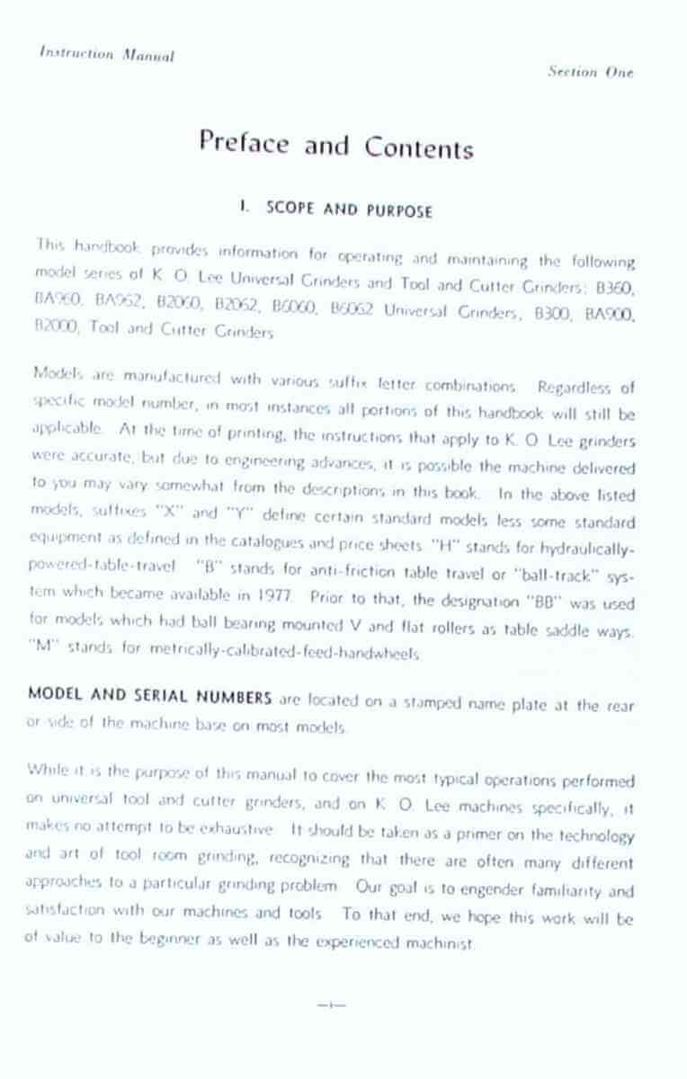
This handbook provides information for operating and maintaining the following model series of K. O. Lee Universal Grinders and Tool and Cutter Grinders: B360, BA960, BA962, B2060, B2062, B6060, B6062 Universal Grinders; B300, BA900, B2000, Tool and Cutter Grinders
The purpose of this manual to cover the most typical operations performed on universal tool and cutter grinders, and on K. 0. Lee machines specifically.

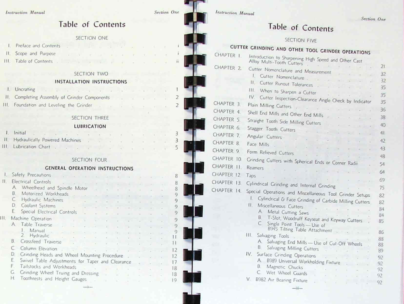
Contents
SECTION ONE
I. Preface and Contents....................................i
II. Scope and Purpose ....................................ii
III. Table of Contents...................................iii
SECTION TWO INSTALLATION INSTRUCTIONS
I. Uncrating...............................................1
II. Completing Assembly of Grinder Components..............2
III. Foundation and Leveling the Grinder...................2
SECTION THREE LUBRICATION
I. Initial................................................3
II. Hydraulically Powered Machines.........................3
III. Lubrication Chart.....................................5
SECTION FOUR
GENERAL OPERATION INSTRUCTIONS
I. Safety Precautions......................................8
II. Electrical Controls....................................8
A. Wheelhead and Spindle Motor........................8
B. Motorized Workheads................................9
C. Hydraulic Machines.................................9
D. Coolant Systems....................................9
E. Special Electrical Controls........................9
III. Machine Operation..................................9
A. Table Traverse.....................................9
1. Manual.........................................9
2. Hydraulic.....................................11
B. Crossfeed Traverse................................11
C. Column Elevation..................................12
D. Grinding Heads and Wheel Mounting Procedure.......12
E. Swivel Table Adjustments for Taper and Clearance..17
F. Tailstocks and Workheads..........................18
G. Grinding Wheel Truing and Dressing................18
H. Toothrests and Height Gauges......................19
SECTION FIVE
CUTTER GRINDING AND OTHER TOOL GRINDER OPERATIONS
1. Introduction to Sharpening High Speed and Other Cast
Alloy Multi-Tooth Cutters.................................21
2. Cutter Nomenclature and Measurement...................32
I. Cutter Nomenclature...................................32
II. Cutter Runout Tolerances..............................35
III. When to Sharpen a Cutter..........................35
IV. Cutter Inspection-Clearance Angle Check by Indicator..35
3. Plain Milling Cutters.................................36
4. Shell End Mills and Other End Mills...................38
5. Straight Tooth Side Milling Cutters...................40
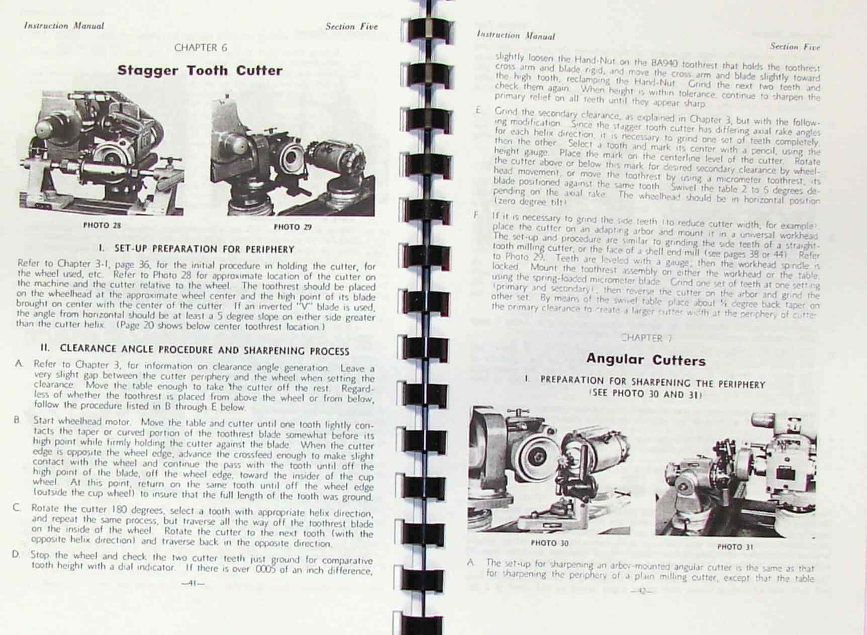
6. Stagger Tooth Cutters.................................41
7. Angular Cutters.......................................42
8. Face Mills............................................43
9. Form Relieved Cutters.................................48
10. Grinding Cutters with Spherical Ends or Corner Radii.54
11. Reamers..............................................64
12. Taps.................................................69
13. Cylindrical Grinding and Internal Grinding...........75
14. Special Operations and Misc. Tool Grinder Setups.....82
I. Cylindrical & Face Grinding of Carbide Milling Cutters.82
II. Miscellaneous Cutters.................................84
A. Metal Cutting Saws................................84
B. T-Slot, Woodruff Keyseat and Keyway Cutters.......85
C. Single Point Tools -Use of
B945 Tilting Table Attachment .......................86
III. Salvaging Tools......................................88
A. Salvaging End Mills -Use of Cut-Off Wheels........88
B. Salvaging Milling Cutters.........................89
IV. Surface Grinding Operations...........................92
A. B989 Universal Workholding Fixture................92
B. Magnetic Chucks...................................92
C. Wet Wheel Guards..................................92
V. B982 Air Bearing Fixture..............................92
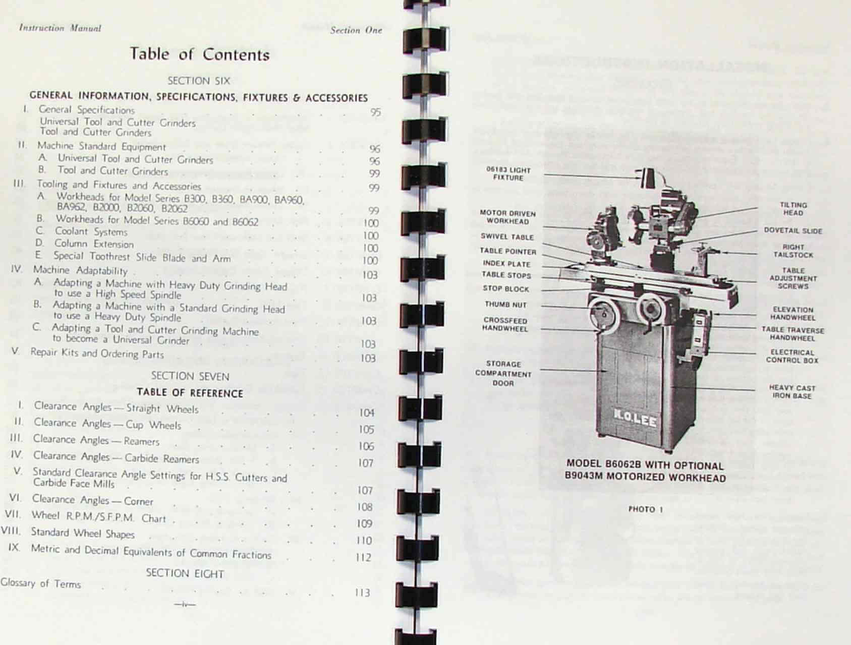
SECTION SIX
GENERAL INFORMATION, SPECIFICATIONS, FIXTURES & ACCESSORIES
I. General Specifications.................................95
Universal Tool and Cutter Grinders Tool and Cutter Grinders
II. Machine Standard Equipment ...........................96
A. Universal Tool and Cutter Grinders................96
B. Tool and Cutter Grinders..........................99
III. Tooling and Fixtures and Accessories..............99
A. Workheads for Model Series B300, B360, BA900, BA960,
BA962, B2000, B2060, B2062 ..........................99
B. Workheads for Model Series B6060 and B6062.......100
C. Coolant Systems .................................100
D. Column Extension.................................100
E. Special Tooth rest Slide Blade and Arm...........100
IV. Machine Adaptability.............................103
A. Adapting a Machine with Heavy Duty Grinding Head
to use a High Speed Spindle.........................103
B. Adapting a Machine with a Standard Grinding Head
to use a Heavy Duty Spindle......................103
C. Adapting a Tool and Cutter Grinding Machine
to become a Universal Grinder....................103
V. Repair Kits and Ordering Parts...................103
SECTION SEVEN TABLE OF REFERENCE
I. Clearance Angles - Straight Wheels...............104
II. Clearance Angles - Cup Wheels....................105
III. Clearance Angles - Reamers.......................106
IV. Clearance Angles - Carbide Reamers...............107
V. Standard Clearance Angle Settings for H.S.S. Cutters &
Carbide Face Mills...............................107
VI. Clearance Angles - Corner........................108
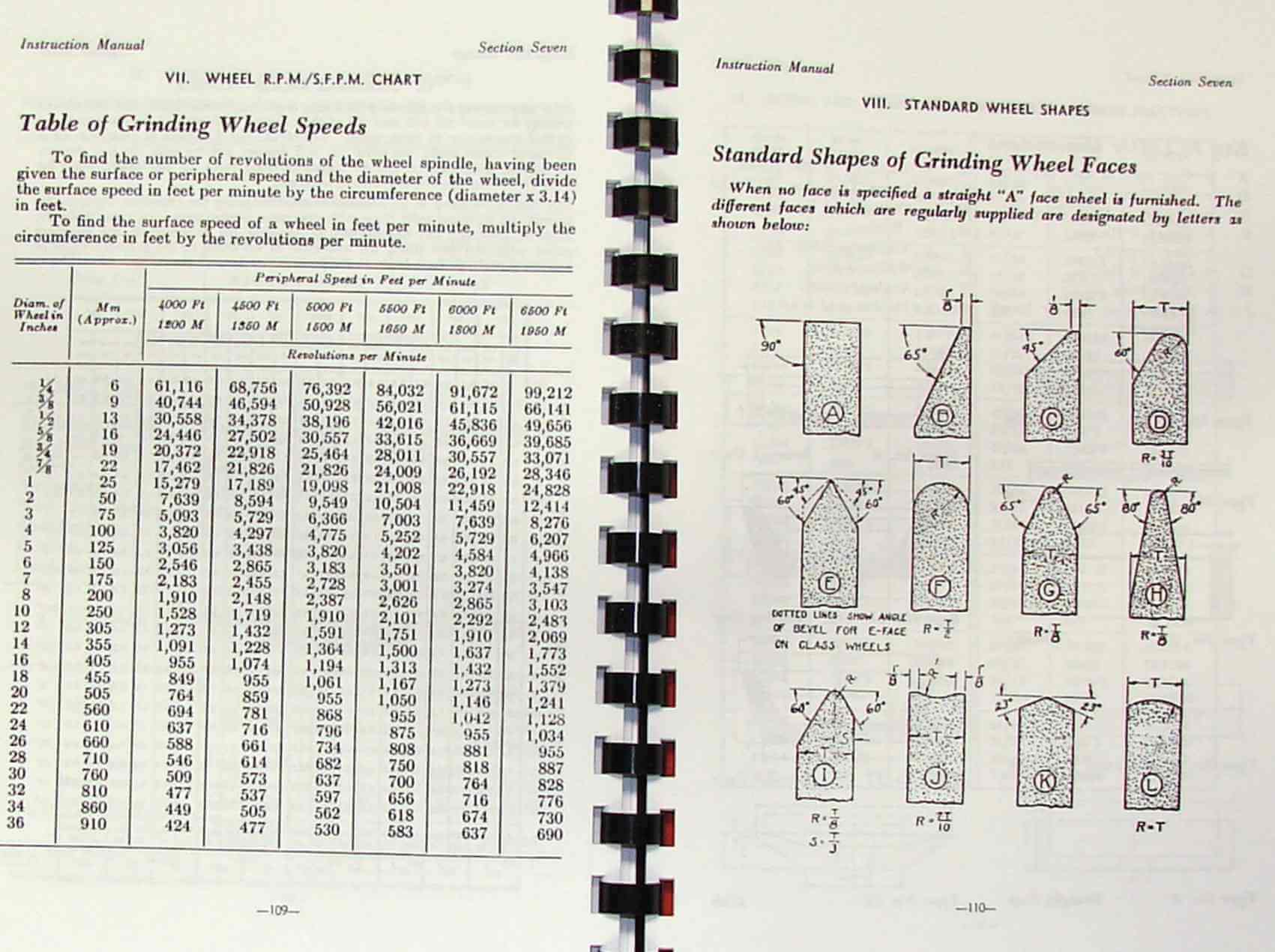
VII. Wheel R.P.M./S.F.P.M. Chart......................109
VIII. Standard Wheel Shapes............................110
IX. Metric and Decimal Equivalents of Common Fractions...112
SECTION EIGHT
Glossary of Terms........................................113


Overview
I have collected this information for many years and have found the information they contain to be priceless in using and setting up the machines properly. I believe this manual will be a valuable resource of knowledge that will provide a lot of helpful information that is often hard to find. My manuals are not photocopies. I maintain a high standard of quality in my reproductions. Most of the manuals I reproduce look better than their originals. I have professionally digitally edited every page, and removed stains, wrinkles and handwriting. All of the manuals are printed on thick white paper to withstand shop wear and tear; they are then comb bound with heavy cover pages so they lie flat on the workbench.