Posted on 4 Comments

How To: Measure the Size and Swing of a Wood or Metal Lathe

measuring lathe swing

People often ask us how to measure the size and swing of their wood or metal lathe. Lathes are generally described by the maximum size of material that can be cut or machined on the lathe. Before machining a workpiece, the following measurements must be considered: the diameter of the work that will swing over the bed and the length between lathe centers. Often you will see numbers like 14×40 or 9×42 describing the size of a lathe. So what do these numbers mean?

Wood and Metal Lathe Sizes

How to Measure the Lathe Swing and Size

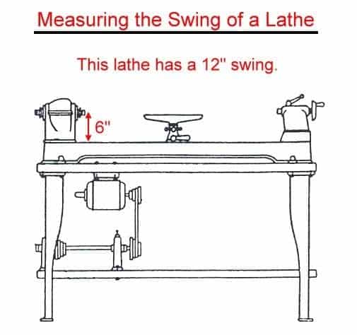
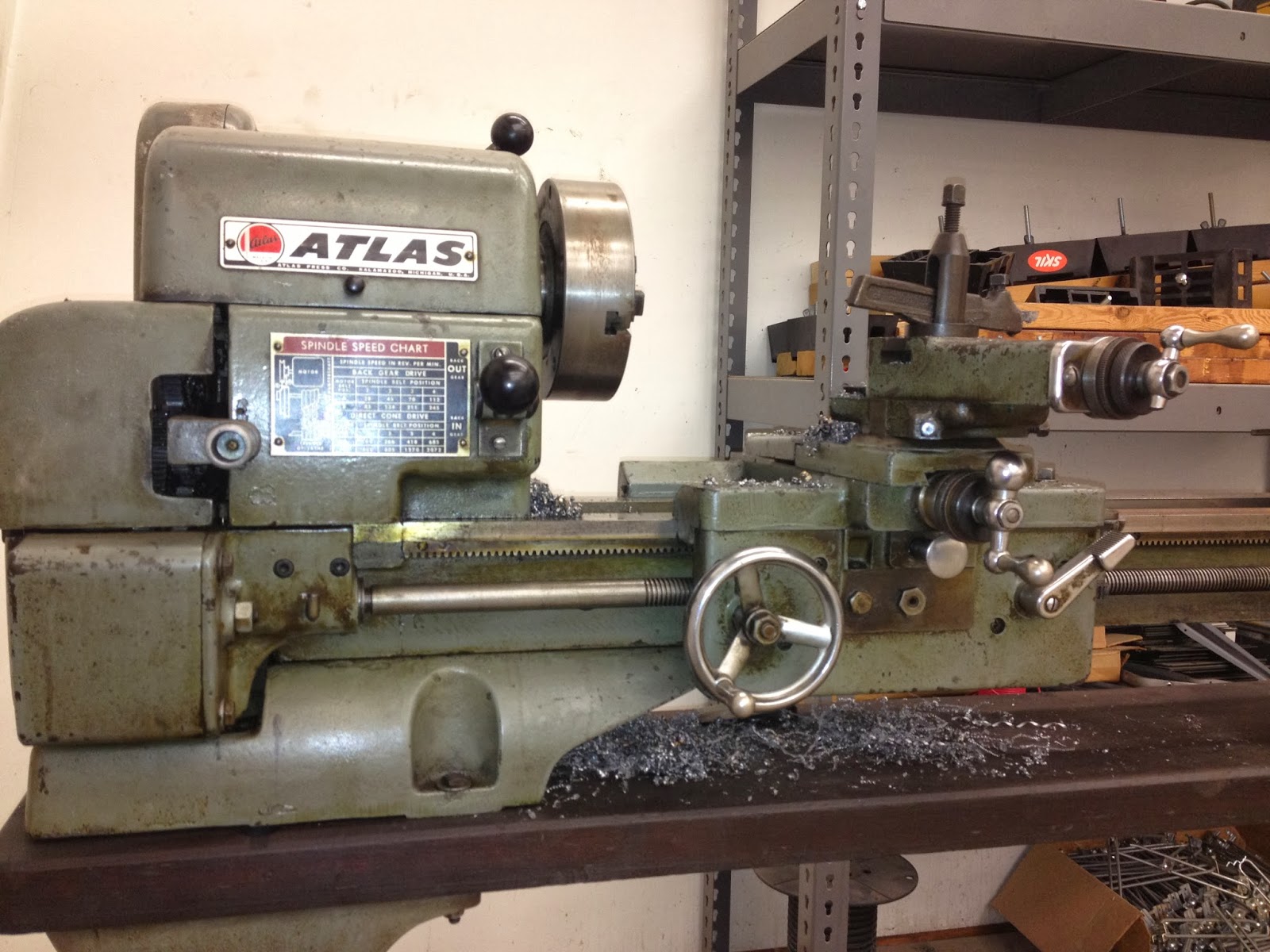
What does the term “swing” on a lathe mean? The first number is referred to as the swing of the lathe which is the maximum diameter of a piece or work that can fit in the lathe. If you have a lathe and want to measure for the swing, you simply measure from the bed of the lathe to the center of the spindle, and then double that measurement. If you measure 6″, then you have a 12″ swing lathe.

Measure Swing of Metal Wood Lathe


  • Special Note: Sometimes there can be some discrepancies between the actual measured swing and the swing the manufactures label the machine as being. I’ve only seen this on larger geared head metal lathes and European metal lathes. Some foreign lathes were made on metric standards, and they rounded to the nearest US standard size. Some companies labeled them based on the measurement from the top of the cross-slide for the tool holder on the metal lathe to the spindle.  For example this Bradford Metalmaster geared head metal lathe series had actual measured swings of 14.5″, 16.5″, and 18.5″, but Bradford labeled the lathes as 12″, 14, and 16″.


Keep in Mind

On metal lathes, it is important to know the swing over the carriage where your tool holder sits. A lot of companies will give you this specification, and some companies in the past have used this measurement as the size of the “actual” swing of the lathe. It is obvious, if you have to cut something over the carriage of the lathe, it will make your working swing smaller in diameter.

Measure Swing of Metal Lathe


How to Measure Distance Between Centers on a Lathe

The second number in the sequence 14x40 is referred to as the distance between centers. This is the distance between a center in the headstock to a center in the tailstock. This gives you an idea as to how long the working area of the lathe is. However, a lot of companies in the 40’s or before used the size of the bed as the second number.

Measure Distance Between Centers Metal or Wood Lathe

Depending on what tooling and what kind of cuts, drills, bores, etc… you are trying to use can vary the maximum length of material you can work on in your lathe.

Example:

A 10×24 lathe can handle work that has a diameter up to 10″ and a length between centers of 24.”

Remember:
If you need any help identifying your lathe please feel free to send us pictures and information to info@ozarkwoodworker.com. We’ve identified hundreds successfully.
Please feel free to post comments and questions on this post or any ideas or topics you would like to discuss on future post. And if you need a manual for your lathe, we have all of them listed here at the links below:

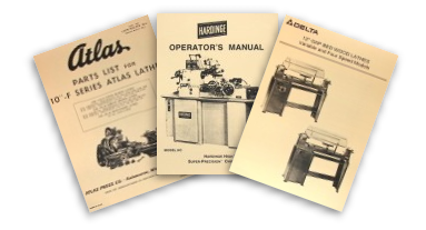
Need a manual for your lathe?

Select the Wood or Metal Lathe links below.


Wood Metal Lathe Manuals
Posted on 1 Comment

Machine ID’d: Delta-Rockwell 11″ Wood Lathe model 46-230

Received these pictures of a Delta-Rockwell 11″ wood lathe on a nice heavy duty bench top stand. These were sold under the Homecraft division of Delta. They made a few different versions that look similar. The earlier models had a steel stand. This one has a cast iron stand and is a model 46-230. This lathe has a serial number of 85-7014, which dates it manufacturing to 1950.

We have a couple manuals that cover the 46-230 Rockwell 11″ wood lathe. We have the owner’s manual with operating instructions and parts diagrams here:
We actually combined the older and new versions of this lathe in one book. We also have “Getting the Most Out of Your Lathe” book that Delta published. It covers this lathe and shows a lot of tips and tricks for using and setting up your lathe for different cuts. This is one book of a 6 part series we have in stock. Here is the book on the lathe:
This lathe originally sold for $54.95 in 1950. Below is the page on the lathe from a 1950 Delta-Homecraft catalog. According to the inflation calculator this is equivalent to $532.50 today.
Do you have one of these lathes, or
do you have anything else you would like to add about it’s history or use?
Please add your comments below.

Submit Your Machine
Do you want to know more about your machine?

Email us your details with pictures, and we’ll put together the best information we can find. Plus, we can get other readers’ input to help you learn more.

Also, feel free to email us if you want us to share your machine on our site.

Email your information to: info@ozarkwoodworker.com

Posted on

Machine ID’d: Atlas 12×36 Bench Top Metal Lathe Model 3983

Received these images of a Atlas 12×36 bench top metal lathe. This is Atlas metal lathe is a model 3983. These were produced in the 60’s. Atlas also made this lathe with a quick change gear box. If you bought this lathe without the quick change gear box, Atlas sold it separately with instructions on how to install it here: ATLAS/CRAFTSMAN 12″ Newer Quick Change Gear Box Installation, Instructions & Parts Manual

The reader said that he had our parts and instructions manual for this lathe, which we have here:
This manual does cover the basics. It explains lubrication, and labels the different controls of the lathe. The reader said that he wanted more information about the operation of the lathe. He’s not the only person that has asked us about this, and that is why we carry the Manual of Lathe Operations and Machinist Tables books, which is full of almost everything you would want to know to get started, plus it contains on the gear and machinist tables for threading.
The problem with these books is that Atlas and Craftsman sold thousands of these over many decades. They made changes to the books as they made changes to the lathes, but they never stated on the cover or in the book which manual covers which vintage and size of lathe. We’ve collected over 20 of these books and have done the research for you, and we have that covers this lathe is the one here:
This book covers the newer style 12″ lathes that Atlas produced, and it specifically covers the one that had a pull-knob to engage the power cross feed. Atlas also made it with a lever mechanism to engage the power cross feed, which we have here. Both books cover the lathe with and without a gearbox.
NO Knob or Lever
Knob
Lever
Do you have one of these lathes, or
do you have anything else you would like to add about it’s history or use?
Please add your comments below.

Submit Your Machine
Do you want to know more about your machine?

Email us your details with pictures, and we’ll put together the best information we can find. Plus, we can get other readers’ input to help you learn more.

Also, feel free to email us if you want us to share your machine on our site.

Email your information to: info@ozarkwoodworker.com

Posted on

10″x50″ Vertical Milling Machine Restoration Part: 1 Unloading :Shop Projects

We received a new 10″ x 50″ milling machine for our shop. It was part of a scratch and dent sale from Grizzly. The mill is a G4029 made in Taiwan. It had a bunch of scratches and dings, plus it was missing a few parts. The variable speed head had parts missing all over it. Something had slammed into the front of the machine damaging the Y-axis lead screw and the bearing bracket. We have a lot of the tools and parts so we are going to be able to fix it up for the price, and make it worth it.

We need a large mill in our shop with a lot of travel to finish some of the CNC machines we are working on, plus make other jigs we need in our shop. We will eventually get this bear of machine up and running with a 3HP variable speed drive head with a VFD from ACER, and add some glass scales with a DRO (Digital Read Out).

Now we are moving it inside. We had them take the arm and head off at Grizzly to make it easier to move, plus they needed a lot of work anyways. We aren’t going to use the original head, and we are going to re-putty and paint the milling machine gray.

We used our aluminum moving truck ramp off our loading dock to help. We were able to find a cart to put the body of the machine on, and to help us up the ramp we used a wench.

It took us a while to get the machine base onto the cart. We also had to brace up the ramp, because it was beginning to bend. I don’t have any picture of the milling machine on the ramp, because we were kind of busy at the time, if you know what I mean.

Stayed tuned. We will be continuing this project. We hope to have this mill up and running by the end of this year.
Do you have a similar project that you would like to share with us or our readers. Feel free to email us or comment below, and we can feature it on our Ozark Shop Talk.

Posted on

Machine ID’d: 1931 South Bend 9″ Metal Lathe

Received these pictures of an old bench top South Bend 9″ metal lathe with a quick change gearbox and vertical drive system. It has serial number 50293 stamp on the tailstock end of the bed.


We have two different manuals that cover this machine and were able to assist this reader. Quality manuals for this older lathe can be difficult to find.


We have a parts manual here:


The parts manuals for all the South Bend lathes, besides the geared head lathes made in the 70’s, combine a large selection of lathes that they manufacturer at one time in one book. Since South Bend offered so many different options and combinations it was easier for them to combine them and let the operator decide what parts pertain to his model in the manual.


The operator’s manual for this vintage of lathe would be contained in the book we have here:


Like the parts manual, South Bend combined a lot of information in the book that covered a variety of styles and models they made at the time. It is important to find the correct version of How to Run a Lathe so it shows you how to set up the correct style of gearbox and other settings. This older version of How to Run a Lathe has been enlarged making it easier to read while still allowing everything to be crisp and clear. We are able to achieve this, because of the high resolution scans we do of all our manual reproductions.

Submit Your Machine
Do you want to know more about your machine?

Email us your details with pictures, and we’ll put together the best information we can find. Plus, we can get other readers’ input to help you learn more.

Also, feel free to email us if you want us to share your machine on our site.

Email your information to: info@ozarkwoodworker.com

Posted on

Machine ID’d: Thompson F Series Surface Grinder

We received an email with these pictures of a Thompson F Series Surface Grinder. We were able to match his surface grinder  to the operator’s and parts manual we have here:

We believe in the late 70’s or early 80’s, Waterbury Farrel bought Thompson.

In the mid 80’s Textron bought Waterbury Farrel and put into the Jones & Lampson group
In the late 80’s Textron sold all of their machine tool assets to Goldman Industrial Group Included were Bryant Grinder, Bridgeport, Jones & Lampson, J&L Metrology and Fellows.
In 2002, Goldman filed for bankruptcy and everything was sold off.
Submit Your Machine
Do you want to know more about your machine?

Email us your details with pictures, and we’ll put together the best information we can find. Plus, we can get other readers’ input to help you learn more.

Also, feel free to email us if you want us to share your machine on our site.

Email your information to: info@ozarkwoodworker.com